by Fred Ridder & Michael Beigel
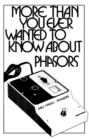
Mention the word “phasor” to most people and they will think you’re talking about those nifty rayguns on Star Trek. Most any contemporary musician, on the other hand, would correctly identify a phasor as the most popular type of electronic sound modification device to come along since the wah-wah pedal of the early ’70s or the fuzz-tone of the late ‘6Os. Yet no more than a handful of those same musicians would be able to adequately describe what a phasor (or phase-shifter) sounds like, and even fewer really understand how a phasor does what it does. This is not very surprising since phasing is a very subtle and sophisticated effect. In fact, it is this subtlety that makes phasing such a universal effect usable in nearly every style of music on anything from pedal steel guitar to synthesizers to amplified vocals or drums.
This article is intended to explain in simple terms the basic acoustical and electronic principles behind the phasing effect. We then also suggest several important qualities the musician should look and listen for when he compares the various phase-shifting devices available at his local music store, for only by actually trying a phasor will a musician find out what phase-shifting can do for his music.
Before we get into what a phasor is, a little historical perspective is in order. Phase-shifters were first developed to try to simulate the so-called “Flanging” effect produced in a recording studio with two tape machines, one of whose heads are deliberately mis-aligned, or whose speed is slightly varied, creating a delay between the two signals. This is the very pronounced shimmering, swooshing sound the authors remember first hearing on “The Big Hurt” single in 1958 (although we’re fairly certain that that was not the first time the effect was used). What phase-shifters actually sound like is somewhat similar to the flanging effect, but the principle and effect produced are actually much closer to a revolving speaker effect, such as the patented and trademarked Leslie system. Recently, electronic devices know as “flangers” have become available which very accurately reproduce the flanging effect; the operation of these devices will be touched upon later in this article. The technology necessary to make electronic phase-shifters and flangers has been known for some time, but it is only in the last few years that the various integrated circuits necessary have become refined enough, reliable enough, and cheap enough to make consumer products practical.
To begin our discussion of phasing, we’ll start at the very beginning –with a single, pure tone sound. The sound we hear is actually a periodic variation in the density or pressure of the air at our ear drum. If we plot this variation in pressure on the vertical axis, versus time on the horizontal axis we obtain the familiar sine-wave curve.
We could also plot the voltage necessary to produce the sound on a loudspeaker, or the voltage the sound would generate as it strikes a microphone, and in either case the result would be exactly the same sine-wave curve. This sine-wave has several important characteristics. The vertical height of the peaks of the curve is the amplitude and corresponds to the loudness of the sound. The horizontal distance between peaks is the wavelength; since the horizontal axis is time, the wavelength corresponds to a period of time, and this time in turn corresponds to the frequency (in “cycles per second” or “Hertz”) or pitch of the sound. One wavelength is defined as 360 degrees because it represents one complete cycle from zero to a maximum through zero to a minimum and back to zero.

One wavelength thus becomes 180 degrees, one quarter is 90 degrees, two wavelengths would be 720 degrees and so on.
If we take two sine-waves of the same wavelength and amplitude and start them at different points in the cycle, they will be identical except one wave will be offset horizontally from the other.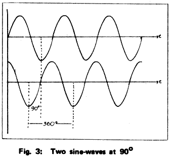
This offset in position is known as the “phase difference” or “phase angle” between the two waves, and is expressed as a fraction or multiple of the 360 degrees per complete cycle. Some further phase differences are shown in.
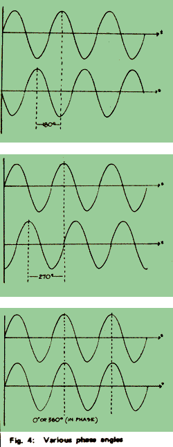
Note that a phase difference of 0 degrees, or 360 degrees (or 720 degrees or any other multiple of 360 degrees) results in the two waves being superimposed, while a phase difference of 180 degrees (or 180 degrees plus a multiple of 360 degrees) results in two waves being mirror images of one another about the horizontal axis. If sounds from two sources strike our eardrum at the same time, the pressure at any instant is simply the sum of the pressure from each source at that instant. This amounts to the same thing as adding two sine-waves by adding the heights of the two waves at each point on the horizontal axis. If we add two waves of equal amplitude and wavelength which are in phase (0 degrees phase difference) the waves reinforce one another and the sum is a wave with the same wavelength but twice the amplitude.
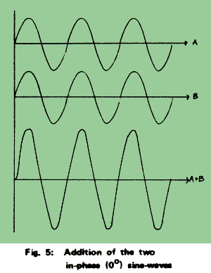
If, on the other hand,the two waves are out of phase (180 degrees phase difference), every positive height on one wave corresponds to an equal negative height on the other,and the result is complete cancellation of the sound, or zero amplitude.
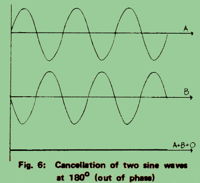
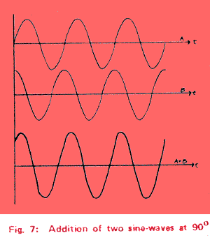
If the phase difference is between 0 degrees and 180 degrees (or between 180 degrees and 360 degrees), the sum will be a wave of the same wave-length, but an amplitude between 0 and 2 times the individual amplitudes .
HARMONIC STRUCTURE OF MUSICAL NOTES
Virtually all musical tones are more complex than the pure sine-wave tones we have discussed so far. A hypothetical musical waveform is shown.
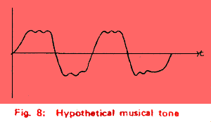
It can be shown mathematically that any complex periodic waveform (that is, one that repeats itself) can be duplicated by adding together a series of sine-waves of appropriate frequencies and amplitudes. The lowest frequency (longest wavelength) sine-wave is known as the fundamental; all the other sine-waves necessary to duplicate the note will be integral multiples of that frequency, and are known as harmonics. For example, if the waveform in Fig. 8 has a fundamental of 100 Hz (cycles per second), the harmonics of the note will be at 200, 300, 500, and so on.
The various harmonics of a note will each have a particular amplitude. In general, the higher the harmonic, the lower the amplitude, although the exact amount is determined by the shape of the complete waveform which is, in turn, a characteristic of the instrument producing the note. For any given note, we can show the harmonic structure on a graph similar to fig 8.

This graph shows the relative amounts of fundamental and harmonics for our hypothetical100 Hz musical tone; the height of the line on the graph corresponds to the amplitude of the particular harmonic.
The amplitude and phase relationships of the harmonics of a note are often referred to as the harmonic structure of that note. It is the harmonic structure that determines the timbre or characteristic sound of the note. Different instruments will have different timbres and thus different harmonic structures. Alternately, if we can modify the harmonic structure of a note, we can change the timbre of the note, although it is not possible to change the timbre sufficiently to make one instrument sound exactly like another.
REVOLVING SPEAKER EFFECT
A revolving speaker system, such as the Leslie, is a very complex, sophisticated electro-mechanical-acoustic device which produces quite a number of subtle electro-acoustic effects simultaneously. One of the simplest yet most important of these effects is related to the Doppler effect. This is the only effect of the many produced by the revolving speaker which we will discuss, as this is the one which relates to electronic phasors.
The Doppler effect refers to the apparent change in frequency when a sound source is moving relative to the observer. A common example is the sound of an automobile’s horn as it approaches, passes, and then recedes from an observer on the side of the road. If a sound source is moving towards an observer, each successive wave emitted by the source will have to travel less distance to reach the observer, and will thus arrive sooner relative to the previous wave. The net result is that the frequency (or pitch) appears higher to the observer. Conversely, if the source is moving away relative to the observer, the pitch is apparently shifted downwards.

If we consider a revolving speaker system and a stationary observer, we see a sound source first moving toward the observer, then away from him due to the revolution of the speaker. According to the Doppler effect, this will result in a periodic change in the pitch heard by the observer. The pitch will rise when the speaker is moving toward the observer and fall when it is moving away. This is basically an acoustical vibrato — a regular variation in perceived pitch of the note.

The case becomes much more interesting if we place this revolving sound source next to a stationary source emitting the same tone. We now have two sound sources whose outputs will either reinforce or cancel one another at the observer’s position depending on the phase relationship at any instant. The perceived frequency of the sound from the revolving source is constantly changing and thus its phase relationship to the constant-frequency source is constantly changing. This results in a periodic cycle of cancellation and reinforcement, rather than the fixed pattern we would obtain with two stationary sources . In other words, we now have an acoustical tremolo in addition to the vibrato described before. This system is the acoustical analog of the electronic phase-shifter.

Thus far we have considered only simple sine-wave signals in the revolving speaker system. If we consider a musical tone, we must take into account the overtones or harmonics in addition to the fundamental tone. In general, the revolving speaker’s effect will be different for each wavelength or frequency. As a result, each harmonic of a musical note will be effected differently by such a revolving speaker system. In other words, we have a fundamental and its harmonics each of which are being effected differently by the system simultaneously. The reader should now begin to appreciate the complexity of this type of effect.
The overall effect is sufficiently complex that the ear and brain cannot distinguish the various individual effects –the DOPPLER — vibrato, the tremolo, the timbre changes caused by the cancellations and reinforcements in the harmonic structure. What we actually perceive is an effect that seems to have something to do with “spatiality” — a kind of spacious, swirling quality. This perception is probably related to the fact that the brain uses phase differences between the two ears in perceiving the space and direction of sounds.
ELECTRONIC PHASE SHIFTERS
The simplified revolving speaker effect just described can be simulated with the electronic circuitry used in phasors or phase-shifters. Many of the subtleties of the acoustical system are lost in the translation, but so are most of the problems associated with an acoustical versus an electronic system, such as physical bulk and the effects of room acoustics. If we look again at the Doppler effect we can see that moving the sound source away from the observer is equivalent to delaying each successive wave crest relative to the preceding one. The amount of time delay must constantly increase to keep each wave crest delayed relative to the one just before it. If the delay stops increasing, the frequency returns to normal; and if we then decrease the delay, the frequency will shift upwards just like moving the sound source toward the observer. In other words, we can simulate the Doppler effect of a revolving sound source with a time delay which can be continuously varied. Real time delay devices are now available — they are what generate the “flanging” effect — but they are complicated and expensive. Commercially available phase-shifters use a different and cheaper type of circuitry which simulates a time delay by generating a phase delay. (If you shift a signal 180 degrees, it is approximately equivalent to delaying it onehalf wavelength). The circuit is basically an “all-pass filter”; that is, a filter which passes all frequencies without a change in amplitude, but with a shift in phase between the input and output. A filter of this type and its phase-shift versus frequency characteristics are shown. By varying the “phase control” in the circuit we can change the phase-shift characteristics as shown. Thus, over a certain range of frequencies, we can vary the amount of phase shift from 0 degrees to 180 degrees.

If we use several of these circuits one after another, we can generate variable phase delays of up to 720 degrees for 4 stages, 1080 degrees for 6 stages and so on. If we electronically combine the phase-delayed signal in equal proportion with a nondelayed signal we will obtain cancellation of all frequencies which are shifted 180 degrees, 540 degrees, or 900 degrees, and reinforcement of these frequencies which are shifted 0 degrees, 360 degrees, 720 degrees, 1080 degrees, and so on. The frequency response of such a phase-shift circuit is shown:
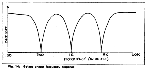
This, by itself, does not make a particularly interesting sound. If, however, we use the “phase control” to vary the phase-shift characteristics, we can move the cancellation and reinforcement points up or down the frequency range as shown:

If we sweep the cancellation up and down the range with a low-frequency oscillator we will have succeeded in creating an electronic unit to generate the same type of swirling effect as the revolving speaker, except much more pronounced due to the larger amount of phase-shift possible. A block diagram of the complete phase-shifter unit is shown:

VARIATIONS ON PHASE SHIFTERS
Flangers
The so-called “flangers” on the market utilize a sophisticated type of integrated circuit known as an “analog delay line”, or “bucket brigade” which generates a pure time delay. The flanging effect was originally generated by using two tape machines deliberately unsynchronized to create a slight time delay between them; it was usually a frustrating trial and error procedure. The flanging units now available reliably and predictably generate variable delays of up to 2 milliseconds–enough to generate very satisfying effects.
The frequency response of a flanger set for a 1 ms delay is shown:

This is the classic “comb filter” response curve. With many instruments, such as most guitars, the differences between the phase-shifter response and the flanger response is not very noticeable; with instruments rich in harmonics, the difference is more pronounced. On a signal with a pseudo-random content, such as cymbals or a synthesizer noise generator, a flanger will produce a distinct musical tonality which sweeps up and down in frequency. This effect is due to the harmonic relationship of the reinforcements; as you can see from the curve of Fig. 17, the peaks occur at every interval of 1 kHz starting at 1 kHz so that the frequencies at each peak are harmonics of the first peak.
The disadvantages of the currently available flangers are related to the newness of the technology. At this time, the necessary integrated circuits are quite expensive and often tend to be noisy or to pick up radio interference. These limitations will probably be overcome as the technology is developed further.
Phasors With Feedback
In developing a prototype bucket brigade phasor for Musitronics Corp. some three years ago, it was discovered that the phasing effect could be greatly enhanced by adding electrical feedback around the phase-shift stages. This design modification creates resonant peaks at the frequencies where reinforcement occurs and thus increases the contrast between the reinforcements and cancellations. If a sufficient amount of feedback is added, the peaks become quite sharp and the phasor will pick out and emphasize individual harmonics of a note as it sweeps up and down the frequency range. The addition of feedback greatly increases the perceived depth of the phasing effect with almost no sacrifice in any other characteristics.
HOW TO SELECT A PHASE SHIFTER
There are literally dozens of phase shifting devices available to musicians, in all ranges of price and performance. What follows is an outline of some of the most important characteristics you should look and listen for, and a discussion of some of the “extras” and convenience functions available on some of the devices.
Depth of Phasing Effect:
This is the first characteristic most people think of when comparing phase-shifting devices. Unfortunately, there are several design characteristics that effect what we perceive as depth. Also, one’s perception of the depth changes as the phasing rate changes; what sounds quite adequate at a moderate rate may be almost undetectable when slowed down or choppy and irritating at a faster rate. Some phasors furnish a “depth” control to compensate for this psychological effect.
The first design factor influencing the depth of the effect is the number of stages. Each two stages will result in one cancellation point in the frequency response curve. Many popular units have 4 stages (2 cancellation points) and some of the new budget models have 2, but the majority of high-quality devices have 6 to 12 stages. The more cancellation points a phasor produces, the closer it approximates the comb-filter and the more satisfying the effect.
The second factor which influences the depth is the width of the frequency range through which the cancellation points sweep, or, more simply, the lowest and highest frequencies which cancel out. If the range is too narrow, the phasing effect sounds shallow, yet if it is too wide it may sound uneven and will probably sound choppy at higher rates.
Two other factors are feedback and distortion. As we discussed earlier, electronic feedback greatly increases the perceived depth without sacrifice in quality. Distortion will also increase the depth by enriching the harmonic content of the signal, but the sacrifices in quality are obvious.
Smoothness of Sweep:
Many musicians consider this to be the most important difference between the various phasing units they try. This characteristic is, however, mainly a matter of personal taste, and some musicians prefer the sweep of one brand for the same reason others despise it. Generally though, the smoother and “rounder” a sweep is, the more people will like it. Phasors whose sweep seems to sweep up or down from one end of the sweep, which have abrupt “corners” at the ends or which have a noticeable unevenness should be avoided unless you like that particular sound.
Sweep Range:
Is the speed continuously variable or are there preset speeds? Is the low speed slow enough and the high speed fast enough? Does the rate control vary the speed smoothly or does it seem to “take off”?
Dynamic Range:
This is perhaps the most important and most overlooked characteristic. It is determined on one end by the residual hum and noise and on the other by the maximum signal the unit can handle without distortion. Most brand-name units are acceptably quiet, but many are limited in “top end”. Most phase-shifters use field effect transistors as the central element in each phase-shift stage; used in this way, an FET may be able to handle only about 1/10th-volt before distorting significantly. Yet hum-bucking guitar pick-ups and many keyboard instruments may produce as much as 2 or 3 volts on peaks. Only the better models available, with photo-modulators or sophisticated IC’s (integrated circuits) can clearly handle such peaks.
On the bottom end, most phasors are quiet enough for normal use, but you should still listen carefully to the noise level if you use high powered amps, a low-output instrument, or if you plan to do any recording.
Foot Switch:
The foot switch should obviously be strong enough to step on. Less obvious, it should not click or pop through the amp, and very importantly, there should be no change in volume when the unit is switched on or off.
Low Impedance Output:
The better units will have an output impedance of 600 ohms or less. This reduces signal loss in cables and allows you to connect directly to a mixer or tape machine.
Battery vs. AC Operation:
Most players prefer AC for reliability. Before you buy a battery unit, find out how long they last and how hard they are to change.
Quality of Construction:
Very simply, will it hold up? And finally, the EXTRAS: Some units offer extra controls and features for additional effects or operating convenience. Some of the more interesting extras include:
- Mike stand socket for mounting the unit
- Pedal control of phasing rate.
- Pedal sweep.
- Square wave sweep.
- Envelope control of rate or sweep.
- Synthesizer interface.
- Stereo phasing.
This is only a partial listing. We suggest trying things out and weighing what you need against what you can afford.
We hope this was not too much more than you wanted to know about phasors, because it is really just the beginning from a designers standpoint. But it should give you all you really need to pick a good phasor and get the most out of it.
Fred Ridder – Marketing Manager for Musitronics Corporation.
Michael Beigel – Vice President in charge of engineering at Musitronics.
